Monday, December 27, 2010

Using the reproduction core support

I got a chance to get a little work done Sunday on the pickup. There is no core support reproduced for the 65-66 2wd F100 pickups, but it doesn't take too long to make the 61-64 reproduction work.

The primary difference between the 61-64 and the 65-66 is the lack of support brackets for the inner fenders on the earlier trucks. Then, Ford changed the radiator mounts for 1966. Do what you want with the radiator support brackets. If they stay, buy a 65 radiator. Remove them and buy a 66 radiator.
First, to make it fit, you have to remove this bracket shown below:
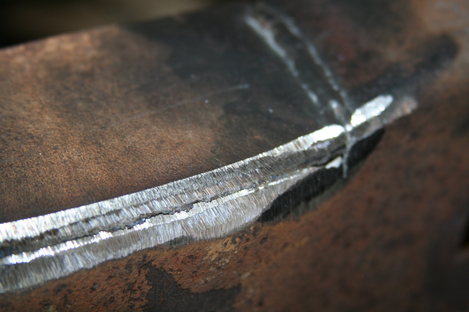
It should be stubbier like this one:
If you are using this and want to keep the 65 style radiator mounts, you'll have to keep the original bracket and swap it over.

Then, I drilled out the spot welds holding the inner fender bracket to the original support. Usually, these are good enough to reuse. If it's really bad, it wouldn't take much to fabricate them out of some angled steel using the original as a pattern.

Next, I had to mock up the front end to find correct placement of the inner fenders:

I took an awl and scratched deep into the core support so that after removing the black primer from the support for welding, I'd still be able to find it.
I used a cupped wire wheel to clean off the primer and shot it with weld through primer.

Then, using the holes made for cleaning off the spot welds, I plug welded the brackets to the support.
You can see in that picture above that I have completely removed the 65 style radiator mount leaving holes where I drilled out the spot welds. I'll fill them in with the MIG for a finished final installation.
For my restoration, it's a lot better to replace a panel than to stitch a rusty old core support back together or pay a mint for a rust-free original only to find out it is rusty. I'm going to have the support blasted clean of the EDP to match the rest of the metal for finishing.

Sunday, October 24, 2010

Frame Repair Part 7

I hope to only have a few more frame repair updates, since there's not too much to look at. I started working my way toward the rear of the truck removing the crossmembers in the frame rails. I also located the front crossmember to the frame rails. It has two locating pins that are about 1" aft of where the centerline of the axles runs. They are just under 3/4" so I measured it all out and put two holes in the frame rails to get it lined up properly.


I also drilled the holes for the core support and lined it up to the frame. That core support is the reproduction for the 61-64 trucks but in a later post, I'll be adapting it to make it work.

After I got that done, I started the process of de-riveting the rear of the truck. There are a bunch. I've found the best way to remove them is to cut them first with the sawzall and then grind off the remainder of the rivet. They are such a pain to remove but there is so much rust hidden between where the crossmembers meet the frame rails, so it just has to be done if this truck is going to last.

In the coming weeks, I'll be rebuilding the 9" rear, patching the frame rails in a few more places, modifying the core support for use in a '66, rebuilding the motor and hopefully getting this messy garage cleaned up a bit.

Monday, October 11, 2010

Frame Repair Part 6

I buttoned up some more repairs today by finish welding the undersides of the welds I previously made. I finished under the core support mounting tabs, behind the crossmember mounting areas and under the cab mount supports.
Here's the front side of the crossmember repair after welding on the rear.
I decided to remove the cab mount supports from the frame rails since I found so much rust behind where the factory spring cups were. I want to make sure the rust is completely cleaned off and out of the crevices before painting or powdercoating the frame. There wasn't a whole lot of rust behind them, but enough that I feel good about removing them to clean it all out. It will make cleaning them easier because I can use the glass bead cabinet rather than trying to work around them on the complete frame rail assembly.
These welds look sloppy, but they will finish out ok once I grind them down.
I also found my transmission. It is a TR3650 from a 2004 Mustang. I got a nice clutch, clutch fork, pressure plate and an aluminum Cobra Flywheel for next to nothing because the transmission grinds between 1-2. There was a recall on these transmission built from 2000-2002 where Ford changed the synchronizer assembly for 1-2 but by 2004, it should already have the good parts installed from the factory. My theory is that either the transmission is a 2000-2002 model and the seller didn't know (or didn't tell me), or that the previous owner just didn't have the clutch adjusted properly. Either way, it may need anything from a set of synchros to a full overhaul with a couple new gears. If it needs a full overhaul, I'll probably find a replacement for it.

Wednesday, October 6, 2010

Frame Repair Part 5

Admittedly, I need to work faster or work more at the same slow pace. This is the same repair as I just made on the driver's side. This time, the passenger's side wasn't nearly as bad, but I still replaced about 12" of frame.


I also got the first chance to mock up the the front crossmember for the first time so I have something to think about. From the first glance, it appears that the engine mounts are a little low, but this could be an illusion since the crossmember isn't flush with the bottom of the frame rails. Also, my intake is very tall, so I might need the extra room to fit the engine under the hood. I welded the back side of the driver's side patch.
As you can see in this picture, I can't wait to clean up the garage a bit. It's gotten filthy with all the grinding and sanding.

Tuesday, October 5, 2010

Frame Repair Part 4

This section of frame rail rotted out where the spring cup was sandwiched against the frame rail. I cut out the bad section and stitched a patch in, rather than just paste some good metal on top of the bad. I first ground both panels into a V at the joints so that I had a nice clean surface to fill with weld and more surface area for the weld to contact.
Clearly, I'm no pro welder, but the penetration is good and it grinds out fine.
I had to go to a flight lesson before finishing the grinding. If you look at the bottom of the patch, it hasn't been ground yet. I will also weld it 100% from the rear too and grind that flush too.

Friday, October 1, 2010

Frame Repair Part 3

Tonight, I finished the front frame rail where the core support bolts. I also removed the front crossmember and spring cups. It was a major undertaking. I went through countless sawzall blades and a couple grinding wheels. The rivets are very difficult to remove. I found more rust in the frame rail. I expected it on the driver's side because I could see it in the spring cup, but the passenger's side was a surprise. It will be easy to fix though.
This patch is from the frame rail of another '66 F100 I parted out years ago, so it's Genuine Claycomo Ford steel in it.My welder was in a good mood.
I cut off the flange and ground it flush for welding.
Very nice finish:
The main suspension crossmember and engine cradle is a bear to remove. I started by cutting it out with a sawzall:
Driver's side looking out from inside where the crossmember was. It was arc welded in at the factory and they did a decent job. Removing the last sections on each side was tough. I haven't ground off the old welds yet.The spring cup was riveted in and the rivets are a huge pain to remove.
My next rust repair:
Passenger's side with the crossmember removed but the spring cup is still in place:
Spring cup removed:
Both front rails when I went in for dinner. I'm almost done working this frame.
Next, I'll remove the boxing steel where the old steering box was because I'll do my own boxing to support the new crossmember.

Tuesday, September 28, 2010

Frame Repair Part 2

On to the driver's side which was much worse. The original placement of the hole was barely distinguishable and I ended up placing the washer about 1/8" further inboard than the passenger's side. The provisions in the cab floor should easily absorb the error, but if necessary, I can widen it just a little bit with a small grinder stone.
This time, I used the sawzall to radially cut outward from the inside. Then, I hit each pie section with the grinder wheel until it could be broken off with the hammer. Making the hole you see below took an entire grinder wheel per side, but I'm happy with the results.

Since this side didn't take up the whole hour this evening that my wife granted me, I moved on to the passenger's side radiator core support mounting place.
I cut out a large section so that the repair wasn't directly over where the rubber radiator core support mount will be. This is overkill since it will be strong enough, but oh well.
Here's the semi-final repair. I won't drill a hole for the core support mount until I have the other side finished and the core support handy so I can get it right. These holes were originally smaller than the holes for the cab mounts, so there is less margin for error. Once the other side is done, I'll get out the hole saw and drag the core support out of storage for fitment.Time expired before I had a chance to do the passenger's side, so I'll have to be happy with tonight's progress. Once I finish that, I'll flip the frame over and weld all the repairs from the bottom side as well. Then, I'll make room for the Crown Victoria front suspension and stack the frame against the wall to make room in the garage for the wife's car. Winter is fast approaching.

Monday, September 27, 2010

Beginning Frame Repairs

Remember this?:

It's fixed now, on one side at least. That's all I could get done in the time I had this evening. The plasma cutter is down right now, so it took a LONG time to cut out the metal to get it to look like this:
Some people just put the patch panel on top of the rusted section. I don't like that type of repair at all since there's always the chance that rust can form between the panels. So I cut a large hole and welded a thick gauge washer in place of the missing metal. If you look closely in the picture above, you can see the washer on the floor below the frame rail. It is a 1.5" zinc plated washer that was just the right thickness to match up well to the existing frame. I ground off the zinc plating to ensure a good weld. Here's how it came out:

More fresh steel comes home


I brought back the rest of the steel from the blaster. I still need to clean a tailgate and the frame, but I won't be using the same blaster. They are only there M-F 8-5 when I have to work and they are an hour from home, so it's just plain inconvenient.
It cost about 1350 and I didn't have to clean up any sand. I don't know if I'll be doing the frame myself or not. I'm tempted to send it out for powdercoating. I need to make the repairs to the frame and then I can worry about who can strip it. The rust on the door literally happened on the way home. Thank you, Missouri Humidity or some splash of water I hit on the way home...who knows...

Friday, September 24, 2010

5.4L DOHC Teardown

I was told this engine had a blown head gasket. The milky oil would help confirm that diagnosis, but during the teardown, I quickly spotted the source of the contamination. Upon further disassembly, I was pleasantly surprised with it's condition. Usually engines suffer apparent damage from oil starvation when water enters the oil to this level. Even the bearings look great. Unless we find cracks in the block or heads, this will be a easy rebuild. I'll measure out the bore tomorrow morning.
Heads are off:
Do you see the problem in the next two pictures?

There's a freeze plug sitting between the oil pump and the oil pan. Both block freeze plugs behind the timing cover were popped out. My theory is that the previous owner bought the car to Kansas City from Georgia (as he told me) where the coolant was replaced with either water or an unsuitable blend of water and antifreeze to keep the coolant from freezing. When it freezes, it pushes on the block freeze plugs. The ones on the outside of the block are going to be tougher to push out of the block than the ones soaked in oil because the outside ones are rusted in place. Rust inside the coolant passage ways confirms water rather than antifreeze coolant being used. The head gaskets looked fine. I hope the two popped freeze plugs were enough to save the block from the pressure of the freezing water. I won't know until it's inspected by the machine shop.


The crank and rod journals look excellent for the amount of water in the oil. They don't really show up in these pictures, but the bearings show very little evidence of scoring and none of the bearings failed.